3. Impression 3D#
This week we learned how to 3D print a piece and we had a session to discuss our documentation in groups of 4. The goals of this week were: * Identify the advantages and limitations of 3D printing * Apply design methods and production processes using 3D printing
3.1 documentation sharing (DAY 1)#
Since some of us still hadn’t begun our documentation, we decided to share tips and to help each other resolve small problems we had with modules 1 and 2. We also shared our piece in OpenSCAD that we would learn to print the next day.
Overall it was a good experience and I hope we will have other chances to discuss together to improve ourselves!
3.2 How to use the printer (DAY 2)#
Here are some tips for you if you want to use the printers of the FabLab: 1. Clean your printer using alcohol –> help prevent adhesion problems 2. Never touch the cross next to the screen –> It will do a reset of the printer 3. Pre-heat your printer if you can –> just a precaution and time-saving
3.3 How to use the PrusaSlicer app#
It’s an app in which you download files to 3D print them in a Prusa printer. The app has an interface which is easy to understand and use. Here are my tips for you if it’s your first time printing in 3D:
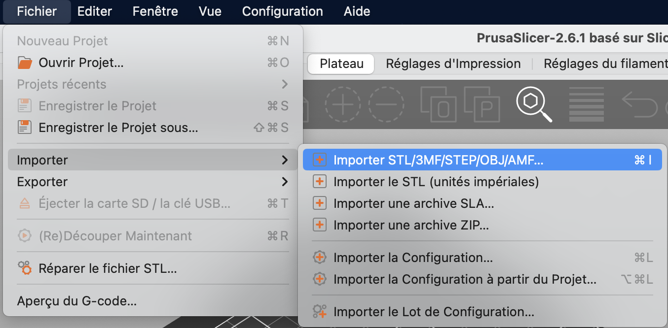
1. To upload a file in the PrusaSlicer app you need to download your file in a format .stl then import it into the app.
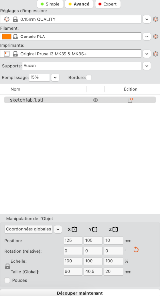
 2. You need to find the right position so that the piece has the most contact with the support. This prevents using too many supports that could be difficult to remove afterward or to prevent the piece from collapsing on itself when printing. The tools on the right of the app can be used to find the good position.
3. You need to choose the printing settings : filling percentage of the piece, type of printer and wire you are using and whether or not supports are needed. You can also change the dimensions of the object
2. You need to find the right position so that the piece has the most contact with the support. This prevents using too many supports that could be difficult to remove afterward or to prevent the piece from collapsing on itself when printing. The tools on the right of the app can be used to find the good position.
3. You need to choose the printing settings : filling percentage of the piece, type of printer and wire you are using and whether or not supports are needed. You can also change the dimensions of the object
 4. After carefully choosing the settings, click on ‘découper maintenant’ in the right lower corner
5. Verify all the information concerning the type of printer you are using, the thread and the filling
6. Export the G-code by tapping on ‘exporter le G-code’ and put it on a SD card
4. After carefully choosing the settings, click on ‘découper maintenant’ in the right lower corner
5. Verify all the information concerning the type of printer you are using, the thread and the filling
6. Export the G-code by tapping on ‘exporter le G-code’ and put it on a SD card
3.3.1 Using the printer#
- Insert the SD card in the printer
- Select your file and start your impression (don’t forget to clean the printer before using it!)
- When your impression is done you can detach it from the support by gently bending the magnetic part (be careful not to touch the part under it because it could burn you!)
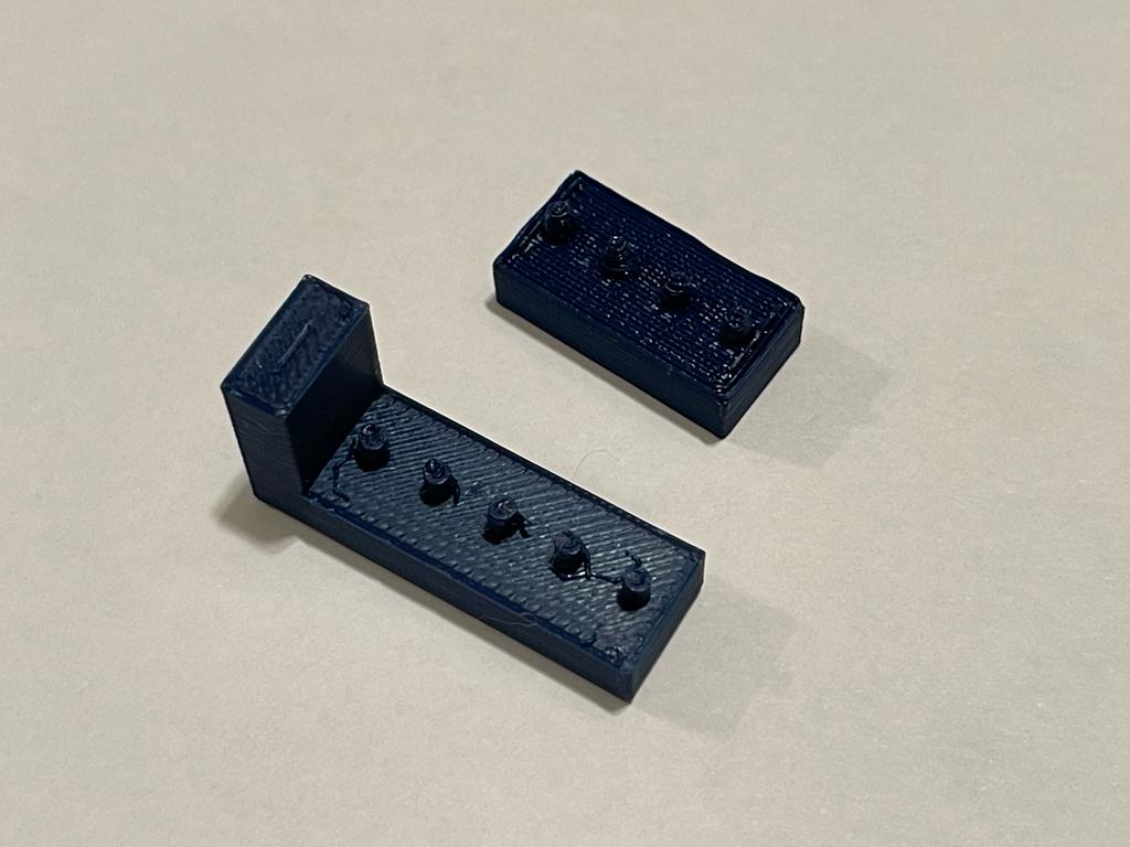
3.4 What we printed#
With Emma, we decided to print a piece each to help us figure out what was the right size for the holes and cylinders so that they will fit well together. Emma printed the piece with the holes and I with the cylinders. To create the piece I usde the code of a student from the last year (Victor De Pillecyn)
\\ FILE : bare_cylindre.scad
\\ AUTHOR : Diane Bilgischer
\\ DATE OF MODIFICATION : 17/10/2023
\\ FROM : Victor De Pillecyn (link to the page: https://fablab-ulb.gitlab.io/enseignements/2022-2023/fabzero-experiments/students/victor.depillecyn/fabzero-modules/module03/)
\\ LICENSE : Creative Commons Attribution 4.0 [CC BY 4.0](https://creativecommons.org/licenses/by/4.0/)

\\ANCHOR parameters
units = 7;
unit_width = 7.8;
unit_height = 9.6/2;
hole_radius = 2.2;
// Other parameters
error=0.01;
$fn = 100;
i=5;

hull(){
        for (i = [0:units-1]){
            translate([unit_width*i, 0, 0])cylinder(h=unit_height, r=unit_width/2, center=true);
        }
    }

for (i = [0:units-1]){
    translate([unit_width*i,0, unit_height])
        cylinder(h=unit_height+error, r=hole_radius+(i*0.1), center=true);
}
The modifications made to the document allowed us to have the following piece :
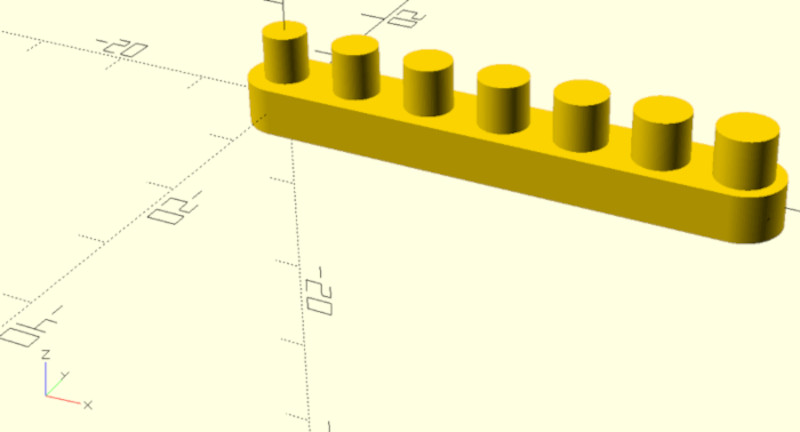
And here is the piece once printed:
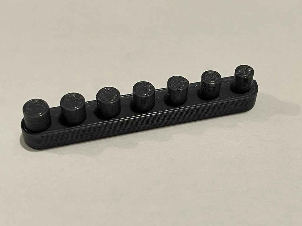
Emma printed another piece that looks like mine but with holes instead of cylinders of my piece. When assembling our two pieces we saw that the right size for the hole was one size higher than the cylinder to allow enough place to be assembled and disassembled easily.
3.5 Module 2 code printed#
The first time I printed my piece, the flexlink in it broke because there was too much tension due to the size of it, so I redid it and we got the final result
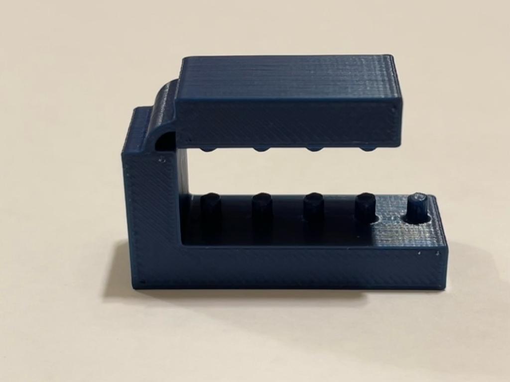 Once we assemble our two pieces together we get:
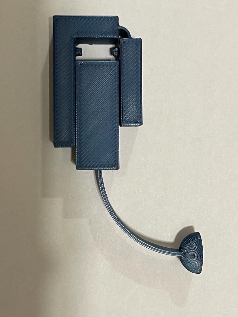
We can see that my piece in both pictures is not the same because the flexlink part on the one that is alone was too thick and wasn’t flexible enough. On the other picture the flexlink part is still not flexible enough to fit the whole piece but since the first time it broke I think the problem comes from the design we did and not the execution. But since the flexlink part still worked a bit on my piece and worked on Emma’s piece we decided it was still a good job since that flexlinks were the main aspect of this work.
If we had to re-do a piece I would have done a piece in 2 parts with a block attached to a flexlink and a cupola who could be attached to it like so :
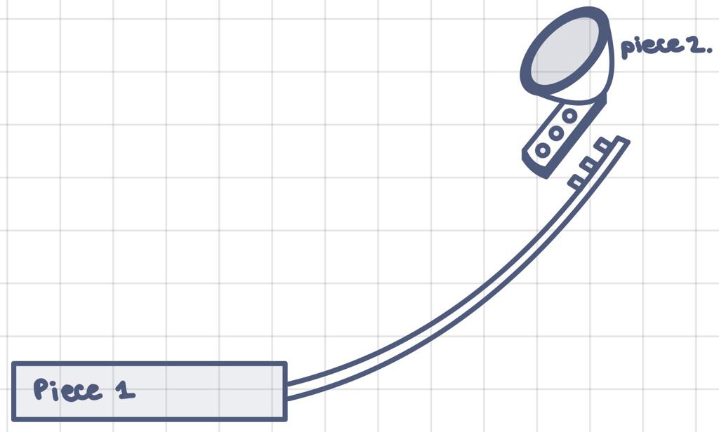
The flexlink on piece 1 would be longer and thin enough to allow more flexibility and the block attached to it should be sized to be big enough to allow to do the catapult throwing. The second piece should be adjust to the size of what we want to throw but still be small enough not to destabilize the piece 1.