4. Computer Controlled Cutting and 3D printing for repair#
This week was a bit different because our group was divided in smaller ones to do different modules. We could choose between two options: 1. electronic prototyping 2. 3D printing for repair + Computer Controlled Cutting And I chose the latter
DAY 1 = 3D printing for repair#
The goals of this formation were: * The basics of repair for electrical appliances * The guidelines for creating a 3D printable version of a spare part needed to repair a product
At the beginning of the class, we repaired a little electrical circuit with a battery and a LED. We had to disassemble it and find the components which were causing the malfunction. In my case it was the battery and a copper wire. After that, the teacher explained to us the different componentes that could be used in an electronical circuit and how to recognize them.
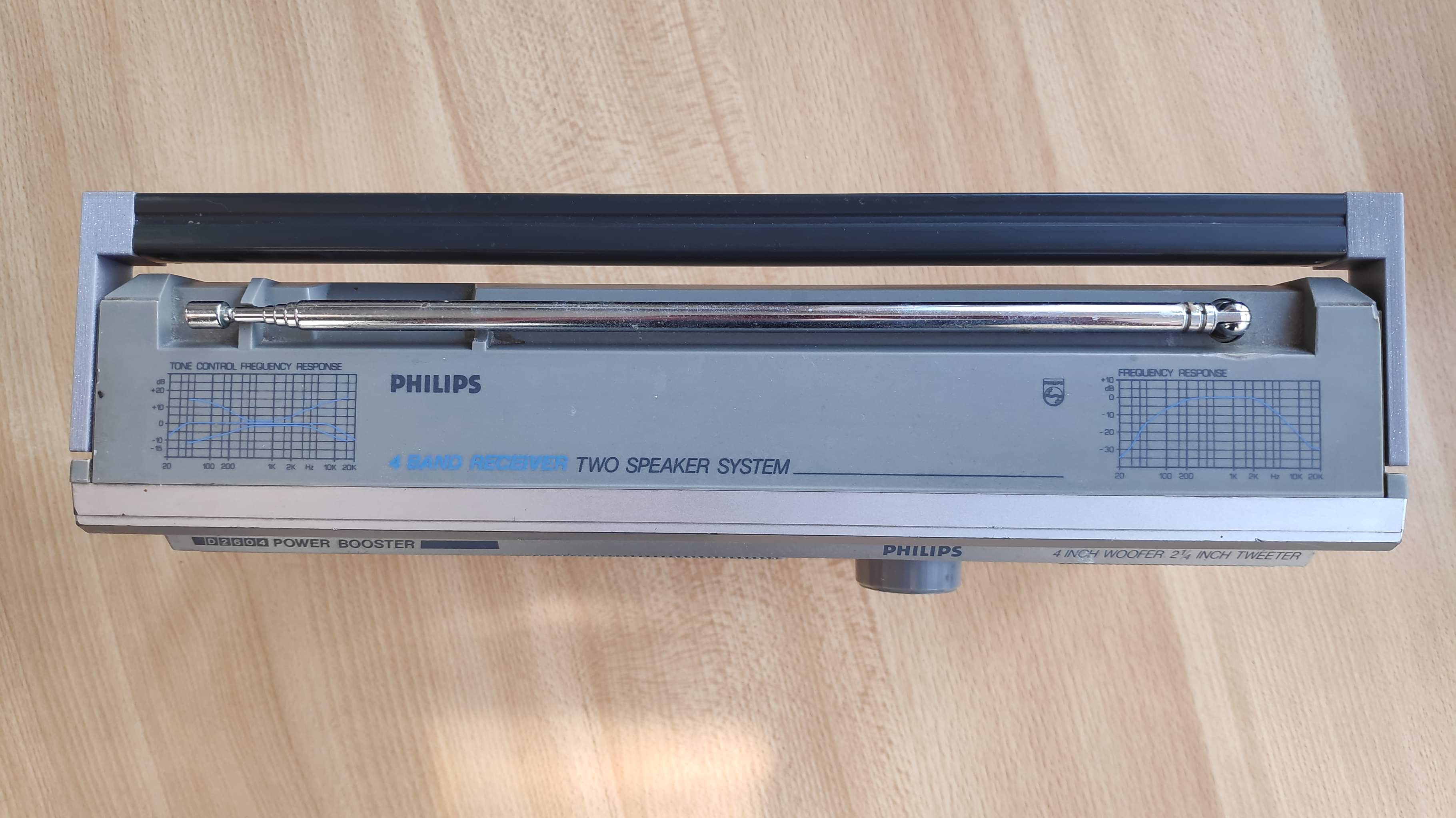
The second part of the course was focused on the 3D printing, first we saw what was in this guide. After that we paired to fix 1 element per group and with Louis we decided to do the hook of the handle of a radio which is present two times on the object. Here is a picture of this piece:
 On this picture, you can also see where the pieces are broken. Both hooks are broken but in different places which is useful because it allows us to analyze the areas of weakness of the piece and therefore the places where we must be careful when repairing it.
schematization#
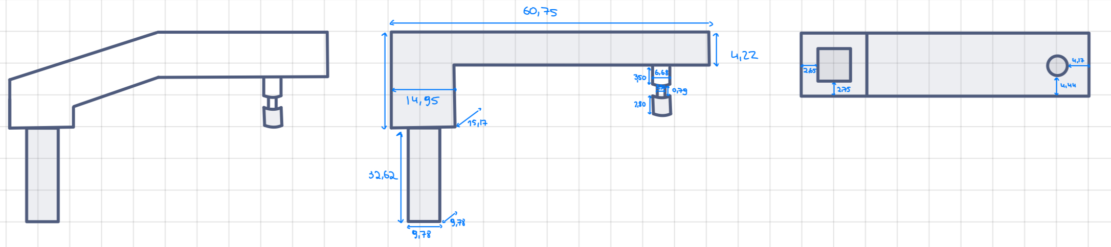
We first made a plan based on the piece we needed to replace and did some alterations to have a piece that is stronger in the weak parts spotted before. These alterations also helped to have more contact between the piece and the support of the printer, therefore a better impression. We ended up with this drawing :
code#
The piece is made up of 3 main parts: 1. The first is a long rectangle which serves as the base of our piece. 2. The second piece is made up of two stacked cubes. This will tighten the part that will fit into the handle. 3. The third and final part is a cylinder with a lamella that has a smaller diameter. This part will fit into the radio and allows the movement of the handle. Since several parts must fit together. We made a first 3D print which was a little more messy (low filling and low quality). We were able to verify if the printing did not pose any technical problems and the measurements were correct once the printing was completed. Unfortunately, the piece had defects: 1. part number 2 which must enter the handle did not come out of it because the measurements were not the good ones and so were too tight. 2. part number 3 also had a defect. The part where the diameter is smaller did not print well. We had to aad support for the second printing
The code after the changes in the parameters is the following:
// Authors : Diane BILGISCHER & Louis JONAS
// Date : October 2023
// License : Creative Commons Attribution-NonCommercial-ShareAlike 4.0 International (https://creativecommons.org/licenses/by-nc-sa/4.0/)

$fn=50;
dim_languette=[60.75,15.17,4.22];
dim_rectangle=[14.95,15.17,12.62];
dim_attache=[9.78,9.78,32.62];
diam_cyl=6.68;
diam_rondelle=3.90;
h_cyl1=3.50;
h_cyl2=2.80;
h_rondelle=0.79;

cube(dim_languette);
cube(dim_rectangle);

translate([2.65,2.75,0])
cube(dim_attache);

translate([49.88+diam_cyl/2,4.44+diam_cyl/2,4.22])
union(){
    cylinder(h=h_cyl1,d=diam_cyl);

    translate([0,0,h_cyl1])
    cylinder(h=h_rondelle,d=diam_rondelle);

    translate([0,0,h_rondelle+h_cyl1])
    cylinder(h=h_cyl2,d=diam_cyl);
}
Here is the end result :
 The top of the piece was not finished because the thread broke during the impression due to tension. Since this part is not seen we decided to not reprint it to save time and PLA wire
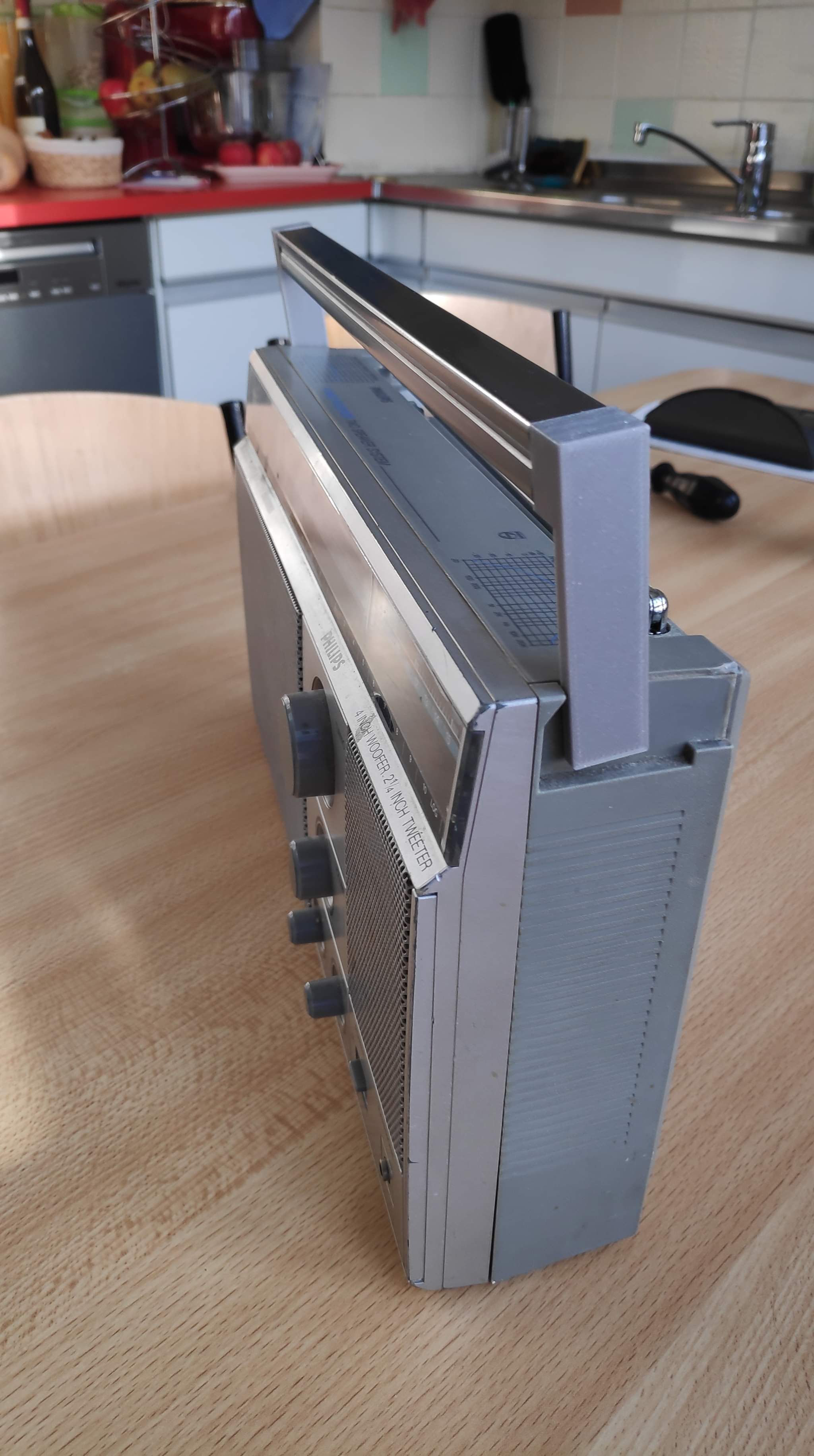
And here is the piece on the radio and functional:
The top of the piece was not finished because the thread broke during the impression due to tension. Since this part is not seen we decided to not reprint it to save time and PLA wire
And here is the piece on the radio and functional:
DAY 2 = Computer Controlled Cutting#
The goals of this unit were
1. to learn how to design and prepare the file and how to cut with a laser cutting machine
2. to determine the kerf of the machine and how to use/assemble the different power, speed, etc.
Important information#
Before using a laser cutting machine, there are a few information that are important to know and which can be find here
Before using the laser cutter : 1. Make sure that you know the material that you are going to cut and therefore if you can use it with a laser cutter 2. Always activate the compressed air and turn on the smoke extractor for the lasersaure 3. Know where the emergency stop button is 4. Know where to find a CO2 fire extinguisher
While using the laser cutter : 1. Wear appropriate protective glasses 2. Do not stare at the impact of the laser beam 3. Stay near the machine until the end of cutting
After using the laser cutter : 1. Do not open the machine while there is smoke inside 2. Remove residue from cutting (if necessary, use a vacuum cleaner)
before using the laser cutter#
To use the laser cutter, you need to have a file with a design in 2D. To create one, you can use the editor Inkscape which is free and open-source. What is interesting about Inkscape is that it is software that allows you to draw using vectors and not pixels. This allows you to be very precise in your drawings. Files with a vector drawing is the type of file we need to use for the lasercutter. You can work on pre-existing files or create new one The interface is easy to understand and use with a wide range of tools to choose from.
The laser printer#
When you want to use a laser cutter, we first need to choose the material we are going to cut or engrave. Depending on that, we will choose the combination of power and speed of the printer. For each material the combination will be different for the same result. Be careful to not mix them up. A higher power implies a bigger chance to cut in one pass but if the power is too high then the material could burn. The speed is linked to the cutting time. If the speed is too high, there is a risk that the cutting will not be done.
the kerf#
Another thing to know before you use your machine is its kerf.
 The kerf is the actual diameter of your laser when cutting and it will change based on a lot of factors:
1. the machine you are using
2. the presets of your machine (automatic on the epilog and manual on the lasersaure)
The kerf is the actual diameter of your laser when cutting and it will change based on a lot of factors:
1. the machine you are using
2. the presets of your machine (automatic on the epilog and manual on the lasersaure)
To measure the kerf, there is a simple test that we can do. We first need to create a design like the following
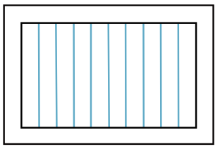
After cutting the file you need to measure the gap between the frame and the rectangles and then you divide the measure by the number of laser passes (here by 11 = blue bars + the inside of the frame which equals to 2 ). In your case we did the test on the epilog cutter and measured a 0.9 mm gap that we needed to divide by 11 which is a really small kerf
2 types of laser cutter#
-
The lasersaure This cutter is an open-source one, that was built at the Fablab. Before using this machine, you need to turn on the compressed air and smoke extractor. Once you import the file, you cannot change the size of the design. This is annoying but doesn’t pose a real problem, we just need to be sure of the design before importing it. The other difficulty with this machine are the settings before cutting (the kerf and the location of the design depending on the material). Those settings need to be adjusted manually.
-
the Epilog It is easy to use but not to maintain because it is not open source. Before using the cutter, you need to turn on the smoke extractor. The kerf is done automatically and the machine has a camera to help place the design easily. This cutter is more precise and easier to use for me.
personal work#
After learning how to use the machines we had to do a personal project. The only instruction was that the final piece needed to be composed of several ones and once they were nested they needed to stay together. To do so we need to pay attention to our kerf !
I create a design on Inkscape of a Christmas tree composed of 2 pieces that will be assembled at an angle of 90 degree.
Here is the design  To make this design, I first made three triangles that I stacked on top of each other from largest to smallest. Then I linked the points together to have the shape of the tree. Finally I curved the lines to have the final design.
Since I did the training on the Epilog laser cutter, I decided to use the lasersaure to challenge myself! It was a bit more difficult at the beginning because a lot of settings are manual opposed to the Epilog but it was a good experience overall!
I almost forgot to turn on the compressed air and smoke extractor but I had the chance to have people with me who reminded me to do it. Before cutting the design I did a test to know the power and speed I needed : power = 800mm/min and speed= 45%. Those settings are a bit high but they allowed cutting in one pass without burning the material.
My first attempt was a failure because I had trouble to adjust the kerf of the lasersaure and forgot that it wasn’t the same as the epilogue. Once I understood that, I tried my second attempt and it was a success!
Here are my two attempts:

We can clearly see the gap on tree number 1 that is not on tree number 2.